ST7789 Display Driver w/ SPI Interface for SAM3X8E MCU [C]
August 21, 2026
Tags: embedded ARMTable of Contents
Summary
The ST7789 is a device controller used in various TFT-LCD displays. The need for a driver arose while planning the infrastructure of my plant monitoring system. This system runs on an SAM3X8E MCU on an Arduino Due development board. The decision to develop a ST7789 driver further led to developing a hardware abstraction layer for the SPI peripheral of the SAM3X8E.
The specific LCD we are working with is the Waveshare 2-inch LCD Module, details of which can be found here.
For the purposes of the plant monitoring system, the functionality can be split into three layers. The hardware abstraction layer handles register write operations and protocols such as SPI. It provides functionality like spi_transfer() to the driver layer. Furthermore, the driver layer has as its purpose to abstract the sending of commands to the ST7789 controller (providing functionality like st7789_draw_rectangle(), for example). Finally, the text drawing interface can use the abstractions provided by the driver layer and let the high-level application use functions like lcd_show_message().
The repository of the plant monitor system can be found here.
SPI Interface
The Serial Peripheral Interface (SPI) is a hardware interface used for communication between microcontrollers and external peripherals.
In typical SPI communication, there may be one Master device and one or more Slave devices. Although there exist both Multiple Master Protocol and Single Master Protocol (both supported by the SAM3X8E), only one device may be in the role of the Master device at any given moment. The Master device controls the data flow and generates the serial clock signal (SCK). The Slave devices have data shifted in and out by the Master device.
A particularity of SPI is that it is a full-duplex interface. Data is shifted out of the Master and into the Slave (MOSI), and out of the Slave and into the Master (MISO) in a single SPI transfer. The Slave Select (NSS, N indicating active-low) signal is asserted by the Master device to select a Slave device to communicate with before initializing a transfer.
Below are listed the typical signals used in SPI and their meanings.
| Signal | |
|---|---|
| MOSI | Master Out Slave In |
| MISO | Master In Slave Out |
| SPCK | Serial Peripheral Clock |
| NSS | (Not) Slave Select |
A number of settings need to be configured before the SPI peripheral is ready for data transfers. The ST7789 controller has its own pre-determined SPI configuration, so we must configure the SAM3X8E to be able to communicate with the ST7789.
Master/Slave mode determines the role of the device during communication. Since we are using Single Master Protocol, the SAM3X8E will be the Master device at all times. The Slave device at a given moment must also be selected. This is done via the NSS (or Chip Select - CS) signal. Further, the Master device can operate in a fixed select mode or a variable select mode. The variable select mode is used when multiple SPI Slave devices are alternated between during runtime.
Next, the SPI clock polarity and clock phase may be configured. The clock polarity determines whether the clock is idle LOW or HIGH. The clock phase determines whether data is sampled on the rising edge of the clock or on the falling edge. This gives a total of four SPI 'modes'. Finally, the number of bits per SPI transfer can be configured (from 8 bits to 16 bits), as well as the master clock divisor, which determines the SPI clock speed.
typedef enum
{
    SPI_MASTER,
    SPI_SLAVE
} spi_role_t;

typedef enum
{
    SPI_FIXED_SELECT,
    SPI_VARIABLE_SELECT
} spi_select_t;

typedef enum
{
    SPI_MODE_0,
    SPI_MODE_1,
    SPI_MODE_2,
    SPI_MODE_3
} spi_mode_t;

typedef enum
{
    SPI_BITS_8 = SPI_CSR_BITS_8_BIT,
    SPI_BITS_9 = SPI_CSR_BITS_9_BIT,
    SPI_BITS_10 = SPI_CSR_BITS_10_BIT,
    SPI_BITS_11 = SPI_CSR_BITS_11_BIT,
    SPI_BITS_12 = SPI_CSR_BITS_12_BIT,
    SPI_BITS_13 = SPI_CSR_BITS_13_BIT,
    SPI_BITS_14 = SPI_CSR_BITS_14_BIT,
    SPI_BITS_15 = SPI_CSR_BITS_15_BIT,
    SPI_BITS_16 = SPI_CSR_BITS_16_BIT
} spi_bits_t;
The SPI lines are controlled by the PIOA controller on the SAM3X8E. Hence, the PIOA clock must be enabled alongside the SPI0 clock before SPI may be used. Moreover, the SPI0 pins must be assigned their PIOA functionality and control must be explicitly handed over to the SPI0 peripheral.
void spi_init(const spi_cfg_t* cfg)
{
    /* Enable clocks for PIOA and SPI0 */
    PMC->PMC_PCER0 |= (1u << ID_PIOA);
    PMC->PMC_PCER0 |= (1u << ID_SPI0);

    /* Select Peripheral A functions for SPI0 pins
     * & give control of SPI0 pins to SPI0 peripheral */
    PIOA->PIO_ABSR &= ~SPI0_PINS;
    PIOA->PIO_PDR = SPI0_PINS;

    /* Configure & Enable SPI0 */
    spi_configure(cfg);
    spi_enable();
}
To configure SPI0, we simply set bits in the appropriate registers of SPIO according to our configuration. The header files provided by Atmel already provide bit-masks for our desired settings.
void spi_configure(const spi_cfg_t* cfg)
{
    /* Configure master/slave mode & chip select */
    SPI0->SPI_MR |= (cfg->role == SPI_MASTER)
                  ? SPI_MR_MSTR
                  : 0;
    SPI0->SPI_MR |= (cfg->select_mode == SPI_FIXED_SELECT)
                  ? SPI_MR_PCS(cfg->chip_select)
                  : 0;

   /* Configure SPI mode */
    switch (cfg->mode) {
        case SPI_MODE_0:
            /* Set CPOL = 0, NCPHA = 1 */
            SPI0->SPI_CSR[cfg->chip_select] &= ~SPI_CSR_CPOL;
            SPI0->SPI_CSR[cfg->chip_select] |= SPI_CSR_NCPHA;
            break;
        case SPI_MODE_1:
            /* Set CPOL = 0, NCPHA = 0 */
            SPI0->SPI_CSR[cfg->chip_select] &= ~SPI_CSR_CPOL;
            SPI0->SPI_CSR[cfg->chip_select] &= ~SPI_CSR_NCPHA;
            break;
        case SPI_MODE_2:
            /* Set CPOL = 1, NCPHA = 1 */
            SPI0->SPI_CSR[cfg->chip_select] |= SPI_CSR_CPOL;
            SPI0->SPI_CSR[cfg->chip_select] |= SPI_CSR_NCPHA;
            break;
        case SPI_MODE_3:
            /* Set CPOL = 1, NCPHA = 0 */
            SPI0->SPI_CSR[cfg->chip_select] |= SPI_CSR_CPOL;
            SPI0->SPI_CSR[cfg->chip_select] &= ~SPI_CSR_NCPHA;
            break;
        default:
            return;
    }

    /* Configure bits per transfer & SPI clock frequency */
    SPI0->SPI_CSR[cfg->chip_select] |= cfg->bits;
    SPI0->SPI_CSR[cfg->chip_select] |= SPI_CSR_SCBR(cfg->mck_divisor);
}
Finally, SPI0 can be enabled.
void spi_enable()
{
    SPI0->SPI_CR = SPI_CR_SPIEN;
}
An SPI transfer consists of writing and reading data from certain registers. The goal is to write count amount of transfers of bits bits each from address tx into the transfer data register (TDR) of the SAM3XE. Simultaneously, we must read the same amount of information from the read data register (RDR).
The SPI status register (SR) provides useful information for debugging. Certain bits are set when the SPI communication is in a particular state. For example, we want to write to the TDR only when all pending data has been transferred as to not overwrite anything. Similarly, we do not want to read from the RDR unless it is full.
void spi_transfer(const void* tx, void* rx, size_t count, spi_bits_t bits)
{
    /* Perform count transfers */
    for (size_t i = 0; i < count; ++i)
    {
        uint16_t tx_word = (bits == SPI_BITS_8)
                         ? ((const uint8_t*)tx)[i]
                         : ((const uint16_t*)tx)[i];

        while (!(SPI0->SPI_SR & SPI_SR_TDRE));

        SPI0->SPI_TDR = tx_word;

        while (!(SPI0->SPI_SR & SPI_SR_RDRF));

        /* If rx is null, ignore RDR contents */
        if (!rx)
        {
            SPI0->SPI_RDR;
            continue;
        }

        if (bits == SPI_BITS_8)
            ((uint8_t*)rx)[i] = SPI0->SPI_RDR;
        else
            ((uint16_t*)rx)[i] = SPI0->SPI_RDR;
    }
}
Waveshare 2-inch LCD Module
Consulting the Arduino Due pinout, we see that pins 2 and 5 correspond to VCC and GND respectively. Moreover, pins 3 and 4 correspond to DIN (that is, MOSI) and SCK. The CS, DC, and RST signals we can map to GPIO as our controller requires us to assert those signals manually.
Moreover, it is specified that the Waveshare 2-inch module supports only 4-line/8-bit communication, so the DC (data/command) signal is required.
ST7789 Controller
Interaction with the ST7789 controller is done through commands described in the ST7789 datasheet. Each SPI transfer must either be a command or data following a command.
The controller supports 3-line/9-bit or 4-line/8-bit communication. In 3-line/9-bit communication, the DC (data control) signal is unnecessary, as each SPI transfer is configured to be 9-bits long, where the 9th bit determines whether the data is a command or parameters to a command. With 4-line/8-bit communication, the DC pin is set to low when the SPI transfer contains a command, and high when it contains data.
The SPI interface of the ST7789 is selected when CS is low. Thus, CS should be asserted from the moment a command is sent until the command's parameter data is transmitted.
static void st7789_write_cmd(uint8_t cmd)
{
    pio_write(PIO_B, CS_PIN, PIO_CLEAR);
    pio_write(PIO_B, DC_PIN, PIO_CLEAR);
    spi_transfer(&cmd, NULL, 1, st7789_cfg.bits);
}

static void st7789_write_data(const uint8_t* data, size_t len)
{
    pio_write(PIO_B, CS_PIN, PIO_CLEAR);
    pio_write(PIO_B, DC_PIN, PIO_SET);
    spi_transfer(data, NULL, len, st7789_cfg.bits);
    pio_write(PIO_B, CS_PIN, PIO_SET);
}
To initialize the ST7789, it is enough to configure all settings to their defaults as specified in the ST7789 data sheet by sending the respective commands and parameters via SPI.
Drawing with the ST7789 is done by first defining the window that is to be filled with pixel data. This is done with the CASET (column address set) and RASET (row address set) commands. Each takes four bytes as parameters that define the starting/ending x-coordinate and starting/ending y-coordinate respectively.
static void st7789_set_window(uint16_t xs, uint16_t xe, uint16_t ys, uint16_t ye)
{
    uint8_t caset_data[] =
    {
        xs >> 8u,
        xs & 0xFF,
        xe >> 8u,
        xe & 0xFF
    };
    uint8_t raset_data[] =
    {
        ys >> 8u,
        ys & 0xFF,
        ye >> 8u,
        ye & 0xFF
    };

    st7789_write_cmd(CASET);
    st7789_write_data(caset_data, sizeof(caset_data));

    st7789_write_cmd(RASET);
    st7789_write_data(raset_data, sizeof(raset_data));

    st7789_write_cmd(RAMWR);
}
The RAMWR command prepares the ST7789 for incoming pixel data. The order in which the data is interpreted depends on the row/column addressing order, which can be configured using the MADCTL and COLMOD commands.
To draw a monochrome rectangle, for example, we can simply set the window, and repeatedly write that colour according to the area of the rectangle. Each pixel is represented by a 16-bit colour.
void st7789_draw_rectangle(const uint16_t xs, const uint16_t xe, const uint16_t ys, const uint16_t ye, const uint16_t colour)
{
    uint8_t pixel_data[] =
    {
        colour >> 8u,
        colour & 0xFF
    };

    st7789_set_window(xs, xe - 1, ys, ye - 1);
    for (uint16_t i = ys; i < ye; i++)
        for (uint16_t j = xs; j < xe; j++)
            st7789_write_data(pixel_data, sizeof(pixel_data));
}
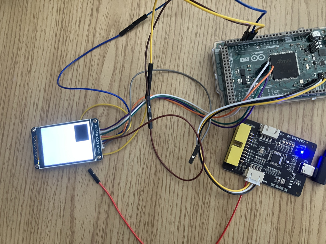
With this, we can test whether we can draw something to the screen. As a simple test, we can try drawing a black rectangle on a white background.
#include "st7789.h"

int main()
{
    st7789_init();

    st7789_draw_rectangle(0x0000, DISPLAY_WIDTH, 0x0000, DISPLAY_HEIGHT, 0xFFFF);
    st7789_draw_rectangle(0x000A, 0x0078, 0x000A, 0x0064, 0x0000);

    while (1);
}
And it works!
Rendering Glyphs
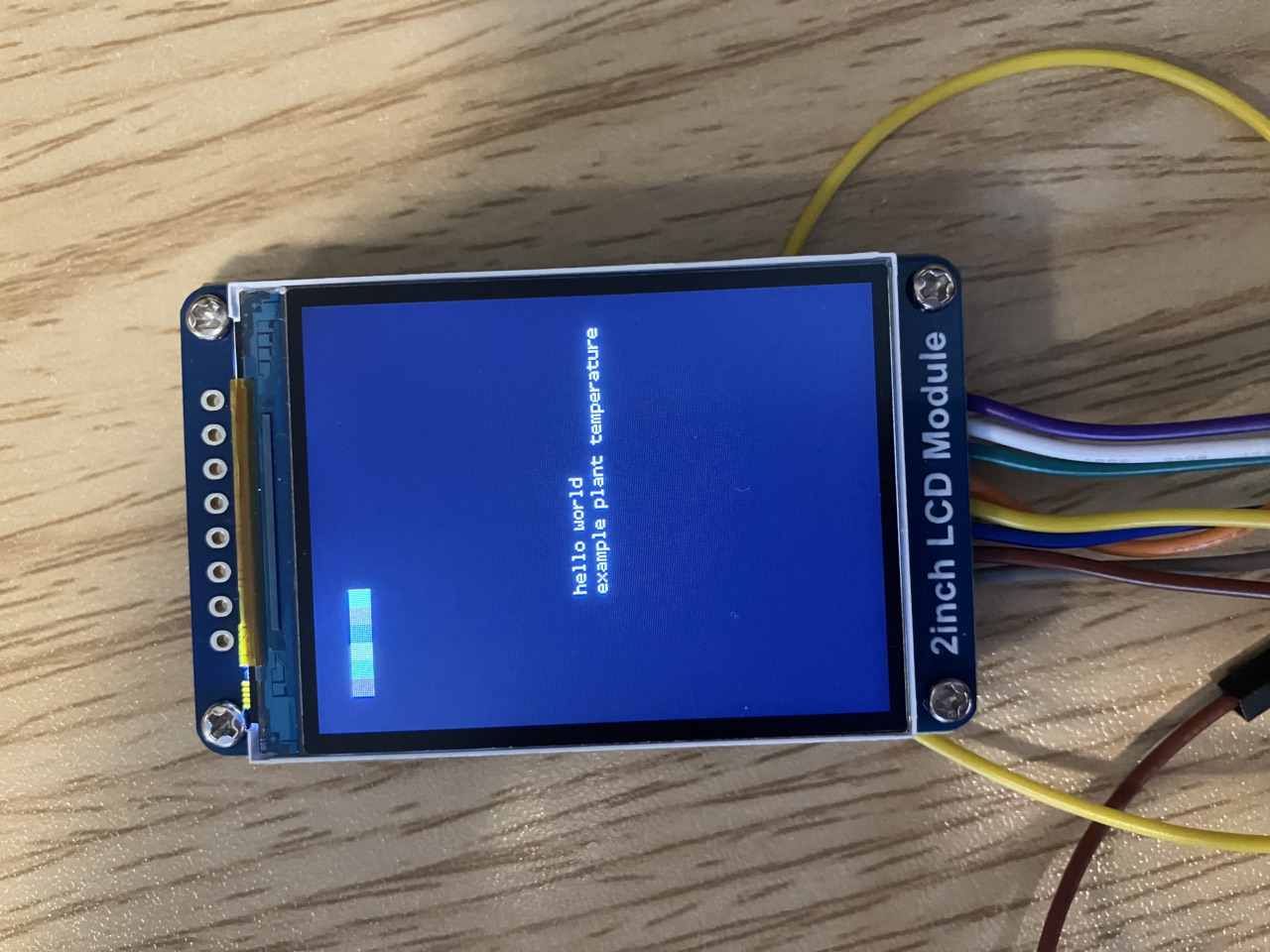
Now that we understand how the controller works, we can render text in a similar manner. can write an intermediate interface between the plant monitoring application and the ST7789 driver for drawing glyphs.
We can select any bitmap font and extract its glyphs' pixel data. Then we can divide the screen area into rows and columns based on the dimensions of the glyphs.
#define BG_COLOR 0x0821
#define FG_COLOR 0xBDF7

#define GLYPH_WIDTH 6
#define GLYPH_HEIGHT 12

#define COLS (DISPLAY_WIDTH/GLYPH_WIDTH)
#define ROWS (DISPLAY_HEIGHT/GLYPH_HEIGHT)

typedef struct {
    uint8_t pixel_data[12];
} glyph_t;

static const glyph_t font[128] = {
    [' '] = {
        .pixel_data = {
            0x00,
            0x00,
            0x00,
            0x00,
            0x00,
            0x00,
            0x00,
            0x00,
            0x00,
            0x00,
            0x00,
            0x00
        }
    },
    ['a'] = {
        .pixel_data = {
            0x00,
            0x00,
            0x00,
            0x00,
            0x70,
            0x08,
            0x78,
            0x88,
            0x78,
            0x00,
            0x00,
            0x00
        }
    },
...
So we can simply draw each glyph by writing FG_COLOR for when a bit of a glyph is set, and BG_COLOR when it is clear.
WIP
Troubleshooting
- The SAM3X8E includes a watchdog timer that is enabled by default. If it is not disabled at the start of the program, the MCU will reset every 16 seconds.
void wdt_disable()
{
    WDT->WDT_MR |= WDT_MR_WDDIS;
}